I. Standard Overview
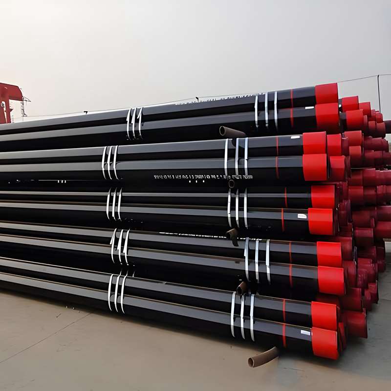
API 5CT is the international standard for oil and gas well tubing (casing and tubing), primarily applicable to drilling, completion, and oil and gas production operations. The standard covers two product categories: API 5CT casing and API 5CT tubing, ensuring the performance and safety of steel tubing used in oil well operations.
II. Materials and Steel Grades
i. Commonly Used Steel Grades for Casing/Tubing
| Steel Grade | Yield Strength (MPa) | Tensile Strength (MPa) | Hardness Max (HB) | Typical Applications |
|---|---|---|---|---|
| J55 | 379–414 | 517–586 | 207 | Casing for shallow wells and low-pressure wells |
| K55 | 379–448 | 517–621 | 207 | Casing for shallow to medium-depth wells; conventional oil well casing |
| N80 | 552–586 | 655–758 | 241 | Casing for medium to deep wells; production casing |
| L80 | 552–621 | 655–758 | 241 | High-temperature, high-pressure well casing; corrosion-resistant wells |
| P110 | 758–827 | 896–1034 | 277 | Casing for high-pressure deep wells; oil & gas extraction wells |
| Q125 | 862–931 | 965–1103 | 321 | Casing for ultra-high-pressure deep wells; special wells |
ii. Chemical composition and mechanical properties
(1) Chemical composition table
| Steel Grade | C (%) | Mn (%) | P (%) | S (%) | Cr (%) | Mo (%) | Ni (%) |
| J55 | ≤0.28 | 0.30–1.06 | ≤0.035 | ≤0.035 | – | – | – |
| K55 | ≤0.28 | 0.30–1.06 | ≤0.035 | ≤0.035 | – | – | – |
| N80 | ≤0.38 | 0.30–1.20 | ≤0.035 | ≤0.035 | – | – | – |
| L80 | ≤0.30 | 0.30–1.10 | ≤0.035 | ≤0.035 | 1.0–1.5 | 0.4–0.6 | 0.4–0.6 |
| P110 | ≤0.32 | 0.30–1.10 | ≤0.035 | ≤0.035 | 0.5–1.5 | 0.2–0.5 | 0.4–0.6 |
| Q125 | ≤0.35 | 0.30–1.20 | ≤0.035 | ≤0.035 | 0.5–1.5 | 0.2–0.5 | 0.4–0.6 |
(2) Mechanical properties table
| Steel Grade | Yield Strength (MPa) | Tensile Strength (MPa) | Max Hardness (HB) |
| J55 | 379–414 | 517–586 | 207 |
| K55 | 379–448 | 517–621 | 207 |
| N80 | 552–586 | 655–758 | 241 |
| L80 | 552–621 | 655–758 | 241 |
| P110 | 758–827 | 896–1034 | 277 |
| Q125 | 862–931 | 965–1103 | 321 |
iii. The main differences between PSL1 and PSL2
| Item | PSL1 | PSL2 |
|---|---|---|
| Applicable Well Conditions | Conventional wells, low-pressure shallow wells | High-pressure deep wells, high-temperature wells, corrosive environments |
| Chemical Composition Control | Less stringent | More stringent |
| Mechanical Properties | Basic requirements | Strict requirements |
| Testing Requirements | Standard/basic testing | Comprehensive testing, often requires third-party verification |
| Cost | Lower | Higher |
III. Specifications and Dimensions
i. API 5CT Sleeve Specification Table
| Nominal OD (mm) | Wall Thickness WT (mm) | Single Length (m) | Tolerance / Deviation | End Type |
|---|---|---|---|---|
| 114.3 | 6.35–12.7 | 9–12 | ±1–3% | Straight Thread (API REG), Buttress Thread (API BTC) |
| 127 | 6.35–14.3 | 9–12 | ±1–3% | Straight Thread, Buttress Thread |
| 133.4 | 6.35–16 | 9–12 | ±1–3% | Straight Thread, Buttress Thread |
| 140 | 6.35–16 | 9–12 | ±1–3% | Straight Thread, Buttress Thread |
| 159 | 6.35–17.5 | 9–12 | ±1–3% | Straight Thread, Buttress Thread |
| 168.3 | 6.35–18.3 | 9–12 | ±1–3% | Straight Thread, Buttress Thread |
| 177.8 | 6.35–19 | 9–12 | ±1–3% | Straight Thread, Buttress Thread |
| 219.1 | 6.35–25.4 | 9–12 | ±1–3% | Straight Thread, Buttress Thread |
| 244.5 | 7.14–28.6 | 9–12 | ±1–3% | Straight Thread, Buttress Thread |
| 273 | 7.14–31.8 | 9–12 | ±1–3% | Straight Thread, Buttress Thread |
| 323.9 | 9.53–38.1 | 9–12 | ±1–3% | Straight Thread, Buttress Thread |
| 355.6 | 9.53–41.3 | 9–12 | ±1–3% | Straight Thread, Buttress Thread |
| 406.4 | 9.53–50.8 | 9–12 | ±1–3% | Straight Thread, Buttress Thread |
| 508 | 12.7–50.8 | 9–12 | ±1–3% | Straight Thread, Buttress Thread |
ii. API 5CT tubing specifications
| Nominal OD (mm) | Wall Thickness WT (mm) | Single Length (m) | Tolerance / Deviation | End Type |
|---|---|---|---|---|
| 60.3 | 6.35–9.53 | 6–12 | ±1–2% | Straight Thread (API REG), Tapered Thread (API IF, NC) |
| 73 | 6.35–12.7 | 6–12 | ±1–2% | Straight Thread, Tapered Thread |
| 88.9 | 6.35–12.7 | 6–12 | ±1–2% | Straight Thread, Tapered Thread |
| 101.6 | 6.35–14.3 | 6–12 | ±1–2% | Straight Thread, Tapered Thread |
| 114.3 | 6.35–16 | 6–12 | ±1–2% | Straight Thread, Tapered Thread |
| 127 | 6.35–16 | 6–12 | ±1–2% | Straight Thread, Tapered Thread |
| 139.7 | 6.35–17.5 | 6–12 | ±1–2% | Straight Thread, Tapered Thread |
| 168.3 | 6.35–17.5 | 6–12 | ±1–2% | Straight Thread, Tapered Thread |
| 177.8 | 6.35–17.5 | 6–12 | ±1–2% | Straight Thread, Tapered Thread |
| 219.1 | 6.35–17.5 | 6–12 | ±1–2% | Straight Thread, Tapered Thread |
IV. API 5CT Casing and Tubing Application and Selection Reference
i. Casing Application and Selection
| Casing Type | Recommended Steel Grade | Typical Well Depth / Pressure | Main Function | Key Selection Points |
|---|---|---|---|---|
| Conductor Casing | J55 | Shallow wells, low pressure | Supports wellhead, prevents collapse | Choose cost-effective and moderate-strength materials |
| Surface Casing | K55 | Shallow to medium wells, normal pressure | Prevents borehole collapse, isolates shallow water zones | Consider wellbore stability and water zone isolation |
| Intermediate Casing | N80 | Medium to deep wells, medium to high pressure | Protects drilling operations, isolates abnormal formation pressure | Steel grade must meet medium-to-high pressure strength requirements |
| Production Casing | L80, P110 | Deep wells, high pressure, high temperature | Supports production zones, withstands high pressure and corrosion | Requires high-strength steel with high-temperature and corrosion resistance |
| High-Strength / Corrosion-Resistant Casing | P110, Q125 | Ultra-deep high-pressure wells or corrosive wells | Used in extreme well conditions and ultra-high-pressure wells | Prioritize high-strength and corrosion-resistant materials |
ii. Application and Selection of Oil Pipelines
| Tubing Type | Recommended Steel Grade | Typical Well Depth / Pressure | Main Function | Key Selection Points |
|---|---|---|---|---|
| Production Tubing | J55, K55 | Shallow to medium wells | Transports oil and gas; connects pump to wellhead | Low-strength, cost-effective grades suitable for shallow wells |
| Medium–Deep Well Tubing | N80, L80 | Medium to deep wells | Withstands medium to high pressure, temperature, and corrosion | Steel grade must match pressure and corrosion conditions |
| High-Pressure Deep Well Tubing | P110 | Deep wells, high pressure, high temperature | Handles high-pressure production; resistant to corrosion and wear | Prefer high-strength grades to ensure operational safety |
| Extreme-Condition Tubing | Q125 | Ultra-deep wells, high pressure, corrosive or CO₂ environments | Used in severe well conditions | Must use high-strength, high-toughness, corrosion-resistant materials |
iii. Summary of key selection points
Steel Grade Selection: Higher well depth and well pressure require higher steel grades. Shallow wells can use J55/K55, medium-deep wells N80/L80, and high-pressure deep wells P110/Q125.
PSL Grade: PSL1 is selected for ordinary operating environments, and PSL2 is selected for complex or high-pressure, high-temperature environments.
Size and Wall Thickness: Select the appropriate outer diameter and wall thickness based on well pressure, depth, and diameter to ensure pressure resistance.
Tube End Type: Casing typically uses straight or grooved threads, while tubing uses straight or beveled threads to ensure reliable connections.
Environmental Factors: High-temperature, corrosive formations, or environments containing CO₂/H₂S require the selection of corrosion-resistant steel grades (such as L80 CR, P110 CR).
V. Corrosion Protection and Coatings
In oil and gas well operations, the corrosion resistance of casing and tubing directly affects pipe life and operational safety. API 5CT standard provides recommendations for the selection of internal and external corrosion protection and coatings for pipes, which must be matched based on the downhole environment, media corrosivity, and operating conditions.
i. Casing Corrosion Protection
| Corrosion Protection Type | Applicable Area | Recommended Coating Thickness | Environmental Matching Recommendation | Description |
|---|---|---|---|---|
| Internal Coating | Inner wall of casing | 0.1–0.3 mm (epoxy or polymer coating) | Suitable for fluids containing water, CO₂, or H₂S | Prevents corrosion from well fluids and formation of rust inside the casing |
| External Coating | Outer wall of casing | 2–3 mm (epoxy primer + polyethylene or polypropylene outer layer) | Corrosive soil or saline environments | Common coatings include FBE, 3PE, and asphalt; selected based on soil pH and moisture conditions |
ii. Pipeline corrosion protection
| Corrosion Protection Type | Applicable Area | Recommended Coating Thickness | Environmental Matching Recommendation | Description |
|---|---|---|---|---|
| Internal Coating | Inner wall of tubing | 0.1–0.2 mm (epoxy or polymer coating) | Suitable for transporting crude oil, natural gas, or water-containing hydrocarbons | Prevents corrosion and scaling caused by the transported media |
| External Coating | Outer wall of tubing | 1–2 mm (epoxy or 3PE coating) | High-temperature wells, offshore wells, or corrosive formations | External coating reduces friction, wear, and formation-induced corrosion |
iii. Key Considerations for Anti-corrosion Coating Selection
Media Type: For environments containing CO₂, H₂S, or brine, a coating with higher corrosion resistance, such as 3PE or epoxy coating, is required.
Temperature and Pressure: High-temperature and high-pressure wells require high-temperature resistant coatings to ensure coating stability.
Pipe Surface Treatment: The surface must be cleaned before applying the anti-corrosion coating, such as through pickling or sandblasting, to ensure adhesion.
Thickness Matching: The outer wall thickness is generally 2–3 mm, and the inner wall thickness is 0.1–0.3 mm, adjusted according to the corrosive environment.
VI. API 5CT Casing and Tubing Inspection Items and Acceptance Standards
| Inspection Item | Method / Standard | Acceptance Criteria / Parameters |
|---|---|---|
| Chemical Composition | Optical Emission Spectroscopy (OES) or Wet Chemical Analysis | Must meet steel grade requirements; PSL1/PSL2 differ in strictness |
| Mechanical Properties | Tensile test, bending test, hardness test | Yield strength, tensile strength, and hardness must meet steel grade standards; PSL1/PSL2 have different strictness levels |
| Visual Inspection | Visual or optical inspection | No cracks, shrinkage cavities, dents, scratches, or welding defects on pipe surface |
| Outer Diameter (OD) | Vernier caliper, ultrasonic gauge | Casing: ±1–3%; Tubing: ±1–2% |
| Wall Thickness (WT) | Ultrasonic thickness gauge | Casing: ±1–3%; Tubing: ±1–2% |
| Single Length | Measuring tape or steel ruler | ±50 mm or ±0.5% |
| Straightness | Straightness gauge or special tools | Max allowable deviation ≤ 0.5% of pipe length |
| Thread Inspection | API 5CT thread gauge | Threads must be complete, undamaged, burr-free, and properly matched |
| Internal/External Coating Thickness | Ultrasonic test or coating thickness gauge | Internal: 0.1–0.3 mm; External: 2–3 mm (casing), 1–2 mm (tubing) |
| Coating Adhesion | Pull-off test or cross-hatch adhesion test | Coating must be firm with no noticeable peeling or delamination |
| Elastic/Bending Test | Bending test | No cracking; permanent deformation ≤ standard limits |
| Pressure Test | Internal or external pressure test | Must meet design pressure ±5%, with no leakage or rupture |
| PSL1 / PSL2 Level Verification | Material Test Certificate (MTC) | PSL1: standard inspection reports; PSL2: third-party MTC verification, stricter compliance |
VII. Selection Criteria and Procurement Recommendations
i. Steel Grade Selection and Well Condition Matching
Shallow Wells / Low-Pressure Wells: J55 or K55 are suitable due to their low cost and ability to meet basic pressure requirements.
Medium-Deep Wells / Medium-High Pressure Wells: N80 or L80 are recommended to ensure pressure resistance and corrosion resistance.
High-Pressure Deep Wells / High-Temperature Wells / Extreme Corrosive Environments: P110 or Q125 are preferred to ensure safety and long-term use.
ii. Casing vs. Tubing Selection Logic
Casing: Primarily used for wellbore support, formation isolation, and well collapse prevention. Key selection criteria are pressure resistance, corrosion resistance, and length matching.
Tubing: Used for oil and gas transportation and downhole operations. Key selection criteria are steel grade, inner diameter, wall thickness, and wear and corrosion resistance.
iii. PSL1/PSL2, Length, Diameter, and Wall Thickness Selection Principles
PSL Grade: PSL1 is suitable for general operating environments; PSL2 must be selected for high-pressure, high-temperature, or corrosive wells.
Diameter and Wall Thickness: Determined based on well pressure, well depth, and flow rate requirements. High well pressure → Increase wall thickness; Well diameter limitations → Select an appropriate outer diameter.
Length: Selected based on well depth and ease of construction, minimizing the number of joints to improve safety and construction efficiency.
iv. Supplier Certification and Quality Control Considerations
Supplier Qualifications: Prioritize manufacturers with API certification, ISO 9001 certification, or third-party testing qualifications.
Material Testing Certificate (MTC): Ensure that the chemical composition, mechanical properties, dimensions, and coating of each batch of pipes meet the standards.
Quality Control: Includes incoming inspection, dimensional and visual inspection, thread inspection, anti-corrosion coating verification, and pressure testing.
Delivery and Traceability: Ensure that each pipe has a clear batch number, length record, and coating information for future traceability and maintenance.